ICO News

Jervois completes U.S. Department of Defense reimbursed drilling at ICO's Sunshine deposit – InvestorsObserver


Jervois completes U.S. Department of Defense reimbursed drilling at ICO’s Sunshine deposit

(TheNewswire)


Highlights:


    • 2.9m calculated true width (“CTW”) @ 0.01% cobalt
      (“Co”), 0.27% copper (“Cu”), 0.03 grams per metric tonne
      (“g/t”) gold (“Au”) (Drillhole SS23-01A)


    • 1.2m CTW @ 0.34% Co, 10.05% Cu, 13.68 g/t Au (Drillhole
      SS23-02)


    • 1.7m CTW @ 0.68% Co, 0.35% Cu, 0.51 g/t Au (Drillhole
      SS23-03)


    • 0.5m CTW @ 1.55% Co, 0.02% Cu, 1.30 g/t Au (Drillhole
      SS23-04)


    • 2.6m CTW @ 0.78% Co, 0.12% Cu, 0.41 g/t Au (Drillhole
      SS23-05)


    • 3.2m CTW @ 0.05% Co, 0.89% Cu, 0.07 g/t Au (Drillhole
      SS23-06A)


    • 0.9m CTW @ 0.07% Co, 1.10% Cu, 0.03 g/t Au (Drillhole
      SS23-07)


  • Cobalt has been declared by the U.S. Government a
    critical mineral, and a reserve or price floor to sustain domestic
    American production has been put forward by the U.S. Congressional
    Select Committee on the Chinese Communist Party (see Jervois ASX
    announcement dated 13 December 2023, “Jervois welcomes U.S.
    Congressional Select Committee proposal for a reserve to sustain
    cobalt price”)


30 January 2024 –


TheNewswire


Australia – Jervois Global Limited
(“


Jervois


” or the


Company


”)


(


ASX:


JRV) (


TSXV:JRV


)
(OTC:JRVMF)


Jervois Global Limited
(“


Jervois


” or the


Company


”) (ASX: JRV)
(TSX-V: JRV) (OTC: JRVMF) is pleased to report results from its
inaugural Sunshine drilling campaign at its Idaho Cobalt Operations
(“


ICO


”) in Idaho,
United States (“


U.S.


”).


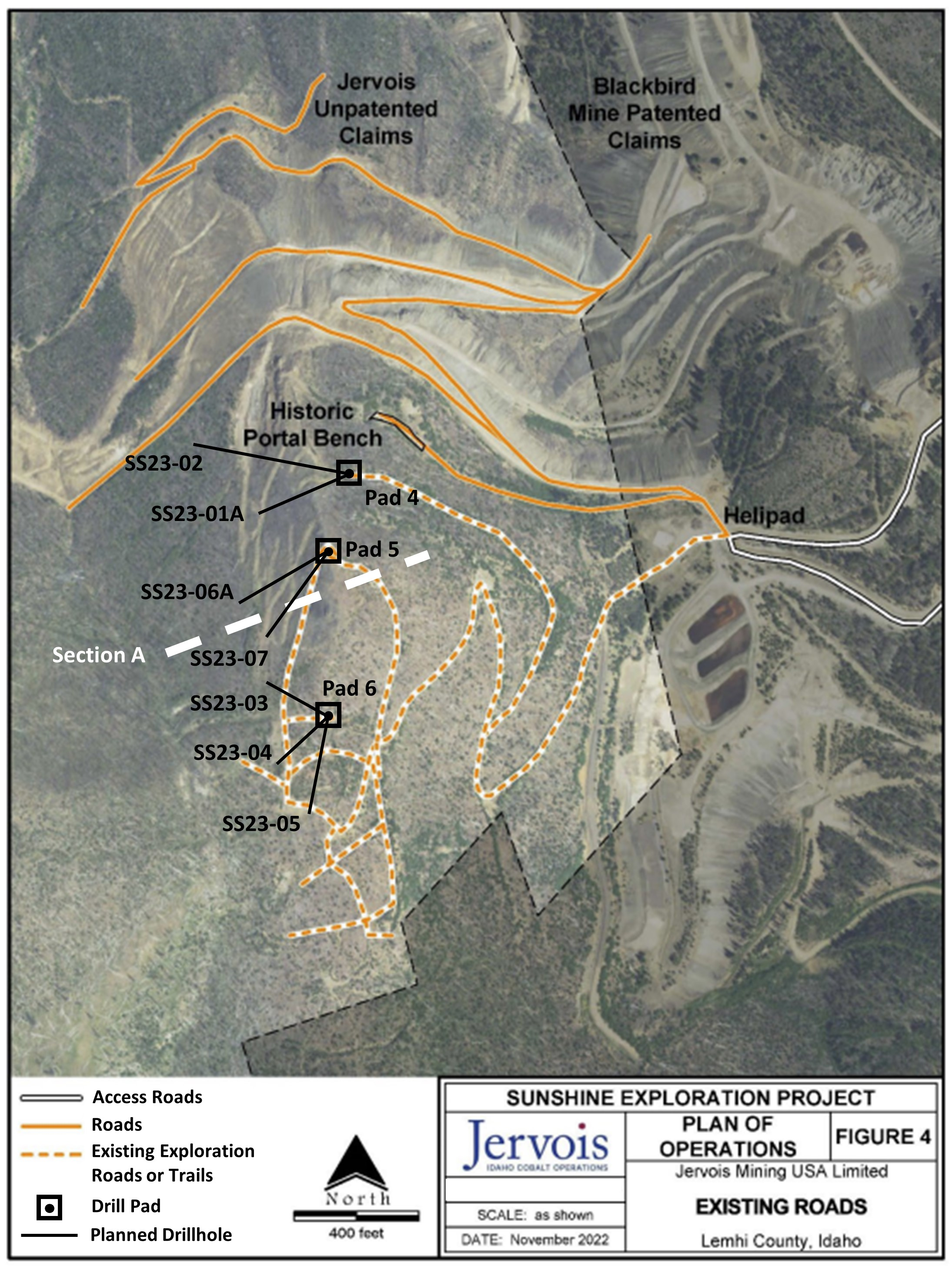
Collar information is provided in Table 1, along with
tabulated analytical results (Table 2), a plan view map showing drill
pad locations (Figure 1) and a cross-sectional overview of drilling
methodology (Figure 2).


Uncapped drill results include:


  • Hole SS23-01A intersected 2.9m CTW at 0.01% Co, 0.27%
    Cu, 0.03 g/t Au.


  • Hole SS23-02 intersected 1.2m CTW at 0.34% Co, 10.05%
    Cu, 13.68 g/t Au. In addition, mineralization was encountered in the
    hanging wall (


    HW


    ”) to
    the Sunshine mineralized horizon, grading 0.42% Co, 0.18% Cu, 0.10 g/t
    Au across 1.0m CTW.


  • Hole SS23-03 intersected 1.7m CTW at 0.68% Co, 0.35%
    Cu, 0.51 g/t Au.


  • Hole SS23-04 intersected 0.5m CTW at 1.55% Co, 0.02%
    Cu, 1.30 g/t Au. Again, additional, mineralization was encountered in
    the footwall (


    FW


    ”) to
    the Sunshine mineralized horizon, grading 0.15% Co, 0.71% Cu, 0.03 g/t
    Au across 2.2m CTW.


  • Hole SS23-05 intersected 2.6m CTW at 0.78% Co, 0.12%
    Cu, 0.41 g/t Au.


  • Hole SS23-06A intersected 3.2m CTW at 0.05% Co, 0.89%
    Cu, 0.07 g/t Au.


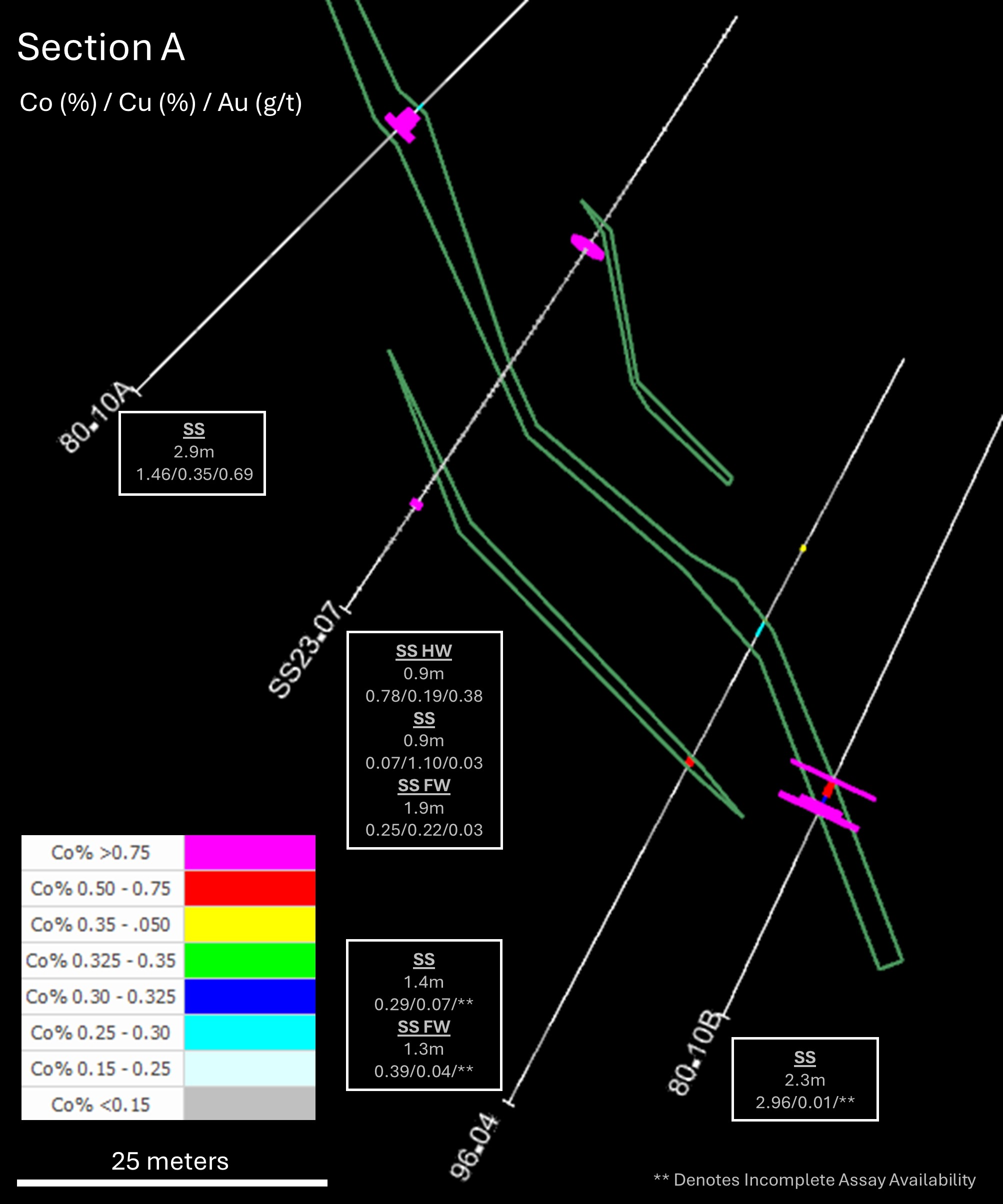
  • Hole SS23-07 intersected 0.9m CTW at 0.07% Co, 1.10%
    Cu, 0.03 g/t Au. In addition, mineralization was encountered in the HW
    to the Sunshine mineralized horizon, grading 0.78% Co, 0.19% Cu, 0.38
    g/t Au across 0.9m CTW, as well as in the FW to the Sunshine
    mineralized horizon, grading 0.25% Co, 0.22% Cu, 0.03 g/t Au.


These drilling results will be utilized to confirm
historic drill intercepts, comprised of 19,000m (104 drillholes) of
core drilling, within the Sunshine deposit and be incorporated
alongside within an updated Australian JORC / Canadian CIM compliant
Sunshine Mineral Resource Estimate (“


MRE


”).


ICO continues with the resource extension programme at
its RAM deposit (see ASX announcement dated 20 November 2023,
“Jervois commences U.S. government-funded resource extension
programme at ICO’s RAM deposit”).


Based on the existing U.S. DoD US$15.0 million
Agreement Funding, costs for these exploration programmes, up to the
end of Q3 2024 for exploration development, drilling, logging,
assaying, MRE modelling and Jervois programme supervision, are fully
reimbursed. The Agreement Funding is under the Manufacturing
Capability Expansion and Investment Prioritization office of
Industrial Base Policy using the U.S. DPA Title III authorities and
utilises funds from the Additional Ukraine Supplemental Appropriations
Act.


Table 1: Sunshine Drillhole Collars


Coordinates *


BHID


(Hole ID)


Easting


Northing


Elevation (m)


Plan Azi


Plan Dip


Final Depth (m)


SS23-01**


199


5459


2414


252


-70


23


SS23-01A


203


5458


2414


230


-80


253


SS23-02


198


5459


2414


286


-50


191


SS23-03


168


5217


2463


298


-51


106


SS23-04


169


5216


2463


235


-51


111


SS23-05


170


5215


2463


184


-45


134


SS23-06**


170


5376


2455


245


-59


123


SS23-06A


169


5376


2455


251


-55


154


SS23-07


172


5377


2455


216


-58


168


*


Coordinates provided in Mine
Grid of RAM Deposit.


**


Drill hole abandoned


prior to mineralized intersection


Table 2: Sunshine Drilling Results


BHID


(Hole ID)


Zone*


From (m)


To


(m)


Calculated True Width** (m)


Cobalt (%)


Copper (%)


Gold (g/t)


SS23-01A


SS


189.7


193.5


2.9


0.01


0.27


0.03


SS23-02


SS HW


163.5


164.6


1.0


0.42


0.18


0.10


SS23-02


SS


180.6


182.0


1.2


0.34


10.05


13.68


SS23-03


SS


82.5


84.7


1.7


0.68


0.35


0.51


SS23-04


SS


55.9


56.6


0.5


1.55


0.02


1.30


SS23-04


SS FW


79.6


82.4


2.2


0.15


0.71


0.03


SS23-05


SS


99.2


104.5


2.6


0.78


0.12


0.41


SS23-06A


SS


131.6


135.1


3.2


0.05


0.89


0.07


SS23-07


SS


146.5


147.5


0.9


0.07


1.10


0.03


SS23-07


SS HW


133.0


134.1


0.9


0.78


0.19


0.38


SS23-07


SS FW


155.8


158.2


1.9


0.25


0.22


0.03


* Sunshine (SS), Sunshine Hangingwall (SS HW), Sunshine
Footwall (SS FW)


** Calculated true widths determined for the composited
intercept mid-point, perpendicular to the down-dip projection of the
Sunshine deposit target models derived from historic Sunshine
drilling


Note:


All grades are reported
uncut for all zones


Figure 1: Sunshine Drill Pad Locations


Click Image To View Full Size


Figure 2: Sunshine Section A Showing SS23-07 in
Relation to Historic Drill Intercepts


Click Image To View Full Size


Quality Assurance


Jervois sent all drill core samples to ALS Global
Laboratories (Geochemistry Division), an independent and fully
accredited laboratory (ISO 9001:2008), in Vancouver, Canada, for
analysis for gold by Fire Assay and multi-element Induction Coupled
Plasma Spectroscopy.


Jervois employs a regimented Quality Assurance, Quality
Control (“


QA/QC


”)
program where at least 10% duplicates, blanks and certified reference
material are inserted into each sample shipment.


On behalf of Jervois Global Limited


Bryce Crocker, Chief Executive Officer


For further information, please contact:


Competent Person’s Statement


The information in this release that relates to Mineral
Exploration is based on information compiled by Andrew Turner, P.Geol.
who is a consultant for the company and a member of The Association of
Professional Engineers and Geoscientists of Alberta.  Andrew Turner
has sufficient experience which is relevant to the style of
mineralisation and type of deposit under consideration and to the
activity which he is undertaking to qualify as a Competent Person as
defined in the 2012 Edition of the ‘Australasian Code for Reporting
of Exploration Results, Mineral Resources and Ore Reserves’.
 Andrew Turner consents to the inclusion in the release of the
matters based on the information in the form and context in which it
appears.


Qualified Person’s Statement


The technical content of this news release has been
reviewed and approved by Andrew Turner, P.Geol., a consultant for the
Company and a Qualified Person as defined by National Instrument
43-101.


Forward-Looking Statements


This news release may contain certain
“Forward-Looking Statements” within the meaning of the United
States Private Securities Litigation Reform Act of 1995 and applicable
Canadian securities laws. When used in this news release, the words
“anticipate”, “believe”, “estimate”, “expect”,
“target, “plan”, “forecast”, “may”, “schedule”,
“expected” and other similar words or expressions identify
forward-looking statements or information. These forward-looking
statements or information may relate to the timing of drilling
operations at ICO, the outcome of the drilling program, timing of an
updated resource model and certain other factors or information. Such
statements represent Jervois’ current views with respect to future
events and are necessarily based upon a number of assumptions and
estimates that, while considered reasonable by Jervois, are inherently
subject to significant business, economic, competitive, political and
social risks, contingencies and uncertainties. Many factors, both
known and unknown, could cause results, performance or achievements to
be materially different from the results, performance or achievements
that are or may be expressed or implied by such forward-looking
statements. Jervois does not intend, and does not assume any
obligation, to update these forward-looking statements or information
to reflect changes in assumptions or changes in circumstances or any
other events affections such statements and information other than as
required by applicable laws, rules and regulations.


Neither TSX Venture Exchange nor its Regulation
Services Provider (as that term is defined in policies of the TSX
Venture Exchange) accepts responsibility for the adequacy or accuracy
of this release.


Appendix 1:


JORC Code, 2012 Edition – Table 1


Section 1 Sampling
Techniques and Data


Criteria


JORC Code explanation


Commentary


Sampling techniques


  • Nature and quality of sampling (eg cut channels, random
    chips, or specific specialised industry standard measurement tools
    appropriate to the minerals under investigation, such as down hole
    gamma sondes, or handheld XRF instruments, etc). These examples should
    not be taken as limiting the broad meaning of sampling.


  • In cases where ‘industry standard’ work has been
    done this would be relatively simple (eg ‘reverse circulation
    drilling was used to obtain 1 m samples from which 3 kg was pulverised
    to produce a 30 g charge for fire assay’). In other cases more
    explanation may be required, such as where there is coarse gold that
    has inherent sampling problems. Unusual commodities or mineralisation
    types (eg submarine nodules) may warrant disclosure of detailed
    information.


All drill core was sampled contingent on geology and
core recovery:


Core was collected directly from the core barrel into
core boxes, and drill core was cut in half by diamond saw, with one
half of the core collected for laboratory analysis and the other half
retained as reference core in the tray. Core trays were clearly
labelled with the hole number, tray number and depth intervals
marked.


A “cut-line” was drawn by the logging geologists
along the length of the drill core as a guide for the core sawing.
 The half-core was sampled, ensuring that the same side is
consistently sampled, and placed into sample bags labelled with the
assigned sample number.  Downhole measurements are recorded using a
Reflex OMNI Gyro at 30 metre intervals down each hole and at 1.5 metre
intervals continuously at the end of every hole.


Field sampling followed Jervois protocols including
industry standard quality control procedures.


Samples were sent to:


ALS
Geochemistry-Vancouver, an independent and fully accredited laboratory
in Vancouver, Canada (“


ALS


”)


for analysis for gold by 30g Fire
Assays with wet chemical finish (ICP) and by multi-element Induction
Coupled


Plasma Spectroscopy (“


ICP


”).  Jervois also has a
regimented Quality Assurance, Quality Control (“


QA/QC


”) program where at least 10%
standards and blanks are inserted into each sample shipment.


Diamond Core: core samples are “representative”
(and not “selective”) in that each sample comprised half (cut)
core that was collected along the entire length of each sample
interval.


Handheld XRF instruments were used to spot check drill
core for mineralization, however those results were not relied on.
 All sample results reported on are from


ALS,
an independent laboratory.


All of the drilling was diamond drill core (HQ/NQ).
 Typically, drill core was sampled on nominal 3 foot (~1m) half core
samples for HQ/NQ.


All sample analyses were completed at ALS.  ALS
operates independent laboratories globally, which are ISO accredited.


Samples are received at the laboratory:  Bar codes are
scanned and logged; samples are weighed and dried; samples are crushed
to 70% less than 2mm, the crushing product is riffle split to collect
a 250g split, which is pulverized to better than 85% passing 75
microns; aliquots from the pulverized split (the sample “pulp”)
are analysed for 34 elements using ICP analysis and for gold by 30
gram Fire Assay with ICP-AES finish.  Any samples with initial
“over-limit” results for specific metals, including gold, copper,
cobalt and arsenic are re-analysed accordingly to achieve complete
results.


Drilling techniques


  • Drill type (eg core, reverse circulation, open-hole
    hammer, rotary air blast, auger, Bangka, sonic, etc) and details (eg
    core diameter, triple or standard tube, depth of diamond tails,
    face-sampling bit or other type, whether core is oriented and if so,
    by what method, etc).


The 2023 surface drilling comprised HQ sized
core.


Holes were generally angled from -55 to -90 degrees at
varying azimuths.


Drill sample recovery


All holes are logged for basic geotechnical
characteristics including measurements and calculations for core
recovery and RQD values.  Core recovery is recorded as a percentage
equivalent to the length of core recovered, as a percentage of the
drill run (interval length).


Excellent recoveries were obtained from the 2023
diamond drilling.


There is no bias noted between sample recovery and
grade.  Excellent recoveries were obtained from Diamond drilling
other than in faulted zones which were not sampled.


Logging


  • Whether logging is qualitative or quantitative in
    nature. Core (or costean, channel, etc) photography.


Diamond


drilling:


Drill core is photographed and logged prior to


sampling;


Core has been geologically and geotechnically logged to
a


level of detail appropriate to support mineral
resource estimation and mining studies.


Logging has been conducted both qualitatively and
quantitatively; full description of lithologies, alteration and
comments are noted, as well as percentage estimates on veining and
sulphides.


The total length of all Sunshine holes drilled in 2023
was 1,263m.  All depths of relevance to this release are listed in
the table in the body of the text.  All drill holes are logged in
their entirety.


Sub-sampling techniques and sample preparation


  • If non-core, whether riffled, tube sampled, rotary
    split, etc and whether sampled wet or dry.


All core was half-cut lengthwise using a diamond saw.
 The HQ/NQ core half-core was sampled.


Samples are received at the laboratory: sample ID bar
codes are scanned and logged; samples are weighed and dried; samples
are crushed to 70% less than 2mm, the crushing product is riffle split
to collect a 250g split, which is


pulverized to
better than 85% passing 75 microns; aliquots from the pulverized split
(the sample “pulp”) are analysed for 34 elements using ICP
analysis and for gold by 30 gram Fire Assay with ICP-AES finish.  Any
samples with initial “over-limit” results for specific metals,
including gold, copper, cobalt and arsenic are re-analysed accordingly
to achieve complete results.


For core sampling the same side is consistently
sampled, half-core is retained in the tray for HQ/NQ.  The assay sub-
sample is placed into sample bags labelled with the assigned sample
number.


One in 20 samples is duplicated where the core is
quartered and a quarter cut sample is analysed as a duplicate.  The
remaining quarter samples is retained in the tray.


Sample sizes of 2-3 kg are appropriate for the grain
size of material.  The sample preparation technique and sample sizes
are considered appropriate to the material being


sampled.


Quality of assay data and laboratory tests


  • For geophysical tools, spectrometers, handheld XRF
    instruments, etc, the parameters used in determining the analysis
    including instrument make and model, reading times, calibrations
    factors applied


    and their derivation,
    etc.


  • Nature of quality control procedures adopted (eg
    standards, blanks, duplicates, external laboratory checks) and whether
    acceptable levels of accuracy (ie lack of bias) and precision have
    been established.


The ICP-AES and Fire Assay (30 gram) analytical
techniques are considered total and are high quality and appropriate
for the mineralization being tested.


Jervois has a regimented Quality Control protocol which
has consisted of systematic submission of blanks, standards and
duplicates in addition to those conducted at the laboratory.


Precision levels for all blanks, standards and
duplicate samples fell within acceptable ranges.


Verification of sampling and assaying


  • Documentation of primary data, data entry procedures,
    data verification, data storage (physical and electronic)
    protocols.


Significant intersections are alternatively verified by
the CP and QP of the company.


No holes have been twinned in this drill
programme.


Data is collected using a PostGRE SQL database
custom-built for Idaho Cobalt Operations and incorporates historic MS
Excel templated data.  The database software includes data validation
algorithms.  The database software also allows for the direct
importation of digital data files from the laboratory.  Data is
backed up on the cloud hosted server on and off site.


All assay/analytical data returning “below detection
limit” results have been entered in the project database as one half
of the detection limit value.


Samples received damaged at the laboratory, or with
insufficient sample weight for analysis had the interval or location
left blank.


Location of data points


  • Accuracy and quality of surveys used to locate drill
    holes (collar and down-hole surveys), trenches, mine workings and
    other locations used in Mineral Resource estimation.


All surface drilling collars were surveyed by licensed
surveyors.  Down-hole surveys were routinely carried out on all holes
using a Reflex OMNI Gyro at 30 metre intervals down each hole and at
1.5 metre intervals continuously at the end of every hole.  Holes
were setup on collar using a Reflex TN14 Gyro.


All datum is collected and recorded in a localized ICO
Mine Grid.


The 3D location of the individual samples is considered
to be adequately established, consistent with accepted industry


standards.


Data spacing and


distribution


Data spacing is considered adequate for the purpose of
the program. The


program’s intent was to
verify historic datasets with the intention of validating historic
drilling spatially and for grade using modern techniques.


The intervals released are within the existing Sunshine
deposit Historic MRE and are interpreted as defining geological
continuity within the various mineralization horizons.  As a result,
this data will be used in a planned mineral resource update later this
year.


The reported drillhole data comprises length-weight
averaged core interval grade values.  Data compositing is completed
during Mineral Resource Estimation, but has not been applied to the
data reported in this release.


Orientation of data in relation to geological
structure


  • If the relationship between the drilling orientation
    and the orientation of key mineralised structures is considered to
    have introduced a sampling bias, this should be assessed and reported
    if material.


Drilling sections are orientated perpendicular to the
strike of the host


rocks where practicable and
moderately oblique where drill access is limited.  Drill holes were
inclined between -55° and -90° to optimize intercepts of
mineralisation with respect to thickness and


distribution.


Drilling with angled holes in most instances provides a
representative sample across the stratigraphy.


Sample security


All individual samples are placed in plastic sample
bags sealed with a cable tie.  Then groups of samples are bagged in
poly-woven sacks also sealed with a cable tie.  The samples are sent
by courier to the lab and tracked.  To date, no sample shipments have
had reported problems and/or a breach in security.


Audits or reviews


Jervois protocols consist of a regimented internal
QA/QC which match or exceed global industry standards.


APEX Geoscience Ltd. has been retained as
independent geological consultants and have reviewed and approved the
ICO sampling protocols and procedures and will be conducting a
thorough review of


the
drill data, including the QA/QC data, prior to the initiation of
resource update.


Section 2 Reporting of
Exploration Results


Criteria


JORC Code explanation


Commentary


Mineral tenement and land tenure status


  • Type, reference name/number, location and ownership
    including agreements or material issues with third parties such as
    joint ventures, partnerships, overriding royalties, native title
    interests, historical sites, wilderness or national park and
    environmental settings.


ICO consists of 358 unpatented mineral claims totalling
2990 hectares (7390 acres).  The claims are 100% owned by Jervois
subsidiary Jervois Mining USA Ltd. and are in good standing.


Unpatented Mineral Claims:


Ownership of unpatented mining claims in the U.S. is in
the name of the holder, with ownership of the minerals belonging to
the United States of America, under the administration of the U.S.
Bureau of Land Management. Under the Mining Law of 1872, which governs
the location of unpatented mining claims on federal lands, the locator
has the right to explore, develop and mine minerals on unpatented
mining claims without payments of production royalties to the federal
government.  Annual claim maintenance and filing fees paid before
September 1


st


each year
are the only federal encumbrances to unpatented mining claims.
 Exploration plans are permitted and administered by the Unites
States Forestry Service.


The United States Department of Agriculture Salmon
Challis National Forest (the Forest Service) issued a revised Record
of Decision (the “


ROD


”) for the ICO in January 2009. The ROD described the
decision to approve a Mine Plan of Operations (“


MPO


”) for mining, milling and
concentrating mineralized material from the ICO.  The ROD was
subsequently affirmed by the Forest Service in April 2009.  The Plan
of Operations at the ICO mine and mill remained unchanged and the ROD
remains in place.  In December 2009, the Forest Service approved the
MPO allowing for the commencement of ICO construction.


There are no known encumbrances.


Exploration done by other parties


The ICO came under Jervois management following the
merger with eCobalt in 2019.  Prior to this merger, the area has a
long history of copper and cobalt exploration and mining.  Copper
mineralization in the Blackbird Creek area was discovered in 1892, and
the area was soon explored as both a copper and gold prospect.  The
area was first mined by Union Carbide at the Haynes-Stellite Mine
located south of the present ICO claim block, during World War I.
 Union Carbide mined approximately 4,000 tons of cobalt-bearing ore
before ceasing operations. From 1938 to 1941, the Uncle Sam Mining and
Milling Company operated a mine at the south end of the present
Blackbird mine and reportedly mined about 3,600 tons of ore.


Calera Mining Company, a division of Howe Sound
Company, developed and


mined the Blackbird
deposit between 1943 and 1959 under a contract to supply cobalt to the
U.S. government.  Calera stopped mining when the government contract
was terminated in 1960.


Machinery Center Inc. mined from the district between
1963 and 1966, when Idaho Mining Company (owned by Hanna Mining
Company) purchased the property.  Noranda optioned the property from
Hanna in 1977 and carried out extensive exploration, mine
rehabilitation and metallurgical testing.  In 1979 Noranda and Hanna
formed the Blackbird Mining Company (BMC) to develop the property.
 BMC completed an internal feasibility study of their property at the
time, including material from the Sunshine deposit in 1982.  BMC
allowed perimeter claims to lapse in 1994, and eCobalt restaked much
of that ground.  From 1995 to the present, eCobalt completed surface
geochemical sampling and drilled 158 diamond drill holes on the ICO
ground.


Geology


Deposit Types:


Whilst the deposits in the Idaho Cobalt Belt have been
studied over many years the deposit types are still a subject of
debate.  Prior to 2005 the overriding opinion was that the deposits
are sedimentary exhalative and are referred to as the Blackbird
Sediment Hosted Cu-Co.  And have been described as stratabound iron-,
cobalt-, copper-, and arsenic-rich sulphide mineral accumulations in
nearly carbonate-free argillite/siltite couplets and
quartzites.


Post 2005 the discovery of high concentrations of rare
earth elements (“


REE


”)
lead to the postulation that the deposits are not volcanogenic massive
sulphide or sedimentary exhalative deposits but instead are iron
oxide-copper-gold (“


IOCG


”) deposits.


Geological Setting:


The ICO is situated in the Idaho Cobalt Belt, a 50- to
55-kilometre long metallogenic district characterized by
stratiform/tabular copper-cobalt deposits.  The deposits are hosted
by a thick, dominantly clastic sequence of Middle Proterozoic age
sandwiched between late Proterozoic quartz monzonitic intrusions.
 The clastic sediments were deposited in a large fault-bounded basin,
probably as large submarine fan complexes and/or deltaic aprons that
were frequently “drowned” by continuing subsidence within the
basin.  All significant copper-cobalt deposits and occurrences are
found in the Proterozoic Apple Creek Formation, which constitutes the
base of this sequence.  This formation was originally correlated with
Pritchard Formation


metasediments of the Belt
supergroup to the north, its age being constrained by dates of 1.37 Ga
for adamellites intruding the sequence and 1.7 Ga from mafic dykes and
sills emplaced along the basin margin faults.


The structure of the Apple Creek Formation is dominated
by the regional rift structure.  Cobalt-copper-gold mineralization
occurs along a northwest-southeast trending structure parallel to and
west of the central axis of the rift.


There is a series of northerly trending faults that are
considered to represent initial growth faults, reactivated by Laramide
and younger events.  The district has also been affected by
north-easterly structures of the Trans-Challis Fault Zone.


The ICO is hosted in Proterozoic age meta-sediments
found on the east side of the central Idaho Batholith comprising
granitic-to-granodioritic rocks.  The Idaho Cobalt Belt represents a
distinct district dominated by stratabound cobalt + copper ± gold
mineralization, with a remobilized constituent.  The district is
underlain by strata of the middle Proterozoic-age Apple Creek
Formation, which is an upward-thickening, upward-coarsening clastic
sequence at least 14,900 metre thick that represents a major
basin-filling episode and was formerly considered part of the Yellow
Jacket Formation.


The Apple Creek can be divided into three units.  The
lower unit of the Apple Creek Formation is over 4,500 metre thick and
consists mainly of argillite and siltite, with lesser occurrences of
fine-grained quartzite and carbonates.  Graded bedding and planar to
wavy laminae are common in the lower unit, which is locally
metamorphosed to phyllite.  The middle unit of the Apple Creek
Formation is up to 1,100 metres thick and comprises several
upward-coarsening sequences of argillite, siltite, and quartzite, with
distinctive biotite-rich interbeds that generally have a direct
correlation to mineralization.  The middle unit hosts the majority of
the known cobalt, copper and gold occurrences in the Idaho Cobalt
Belt.  The upper unit exceeds 3,000 metres in thickness and is
predominantly composed of thin- to thick bedded, very fine- to
fine-grained quartzite.


Mafic tuffs within the Apple Creek Formation are the
oldest igneous rocks exposed in the Sunshine-Blackpine district.
 They are accompanied by felsic tuffs and carbonatitic tuffs. Some
mafic dikes and sills intrude the Apple Creek Formation and may be
comagmatic with the mafic tuff beds.  Several small lamproitic
diatremes may also be coeval with mafic volcanism.


The Apple Creek Formation has undergone varying degrees
of regional


metamorphism, ranging from
greenschist facies in the southern part of the district to amphibolite
grade facies in the northern part of the district.  Several types of
mafic dikes and sills, ranging from 1m to 30m thick, intrude the Apple
Creek Formation and are interpreted as feeders to the exhalative mafic
tuffs, which are most abundant in areas of intrusive activity.


Style of Mineralization:


Mineralization at the ICO is characterized as
syngenetic, stratiform/tabular exhalative deposits within, or closely
associated with, the mafic sequences of the Apple Creek Formation.
 This mineralization is dominantly bedding concordant and the
deposits range from nearly massive to disseminated.  Some
crosscutting mineralization is present that may be in feeder zones to
the stratiform mineralization or may be due to remobilization locally
into fracture quartz veins and/or crosscutting structures.


Dominant minerals include cobaltite (CoAsS) and
chalcopyrite (CuFeS2), with lesser, variable occurrences of gold.
Other minerals present in small quantities are pyrite (FeS2),
pyrrhotite (FeS), arsenopyrite (FeAsS), linnaeite ((Co Ni)3S4),
loellingite (FeAs2), safflorite (CoFeAs2), enargite (Cu3AsS4) and
marcasite (FeS2).


Recently, rare-earth minerals have been identified in
samples from the deposit as monazite, xenotime and allanite.  At this
time, these minerals have not been considered for potential recovery
as by-products of the Co-(Cu-Au).


The RAM is the largest and best-known deposit in the
ICO area.  It consists of a Hanging-wall Zone with 3 primary and 4
minor horizons, a Main Zone comprising 3 horizons, and a Footwall Zone
with 3 horizons.  These sub-parallel horizons generally strike N15oW
and dip 50o – 60o to the northeast.  Most of the significant Co
mineralization is associated with exhalative lithologies i.e. biotitic
tuffaceous exhalate (BTE), siliceous tuffaceous exhalate (STE), and
quartzite with impregnations of biotitic tuffaceous exhalate (QTZ/BTE)
or siliceous tuffaceous exhalate (QTZ/STE).


Drill hole Information


  • A summary of all information material to the
    understanding of the exploration results including a tabulation of the
    following information for all Material drill holes:


    • easting and northing of the drill hole collar


    • elevation or RL (Reduced Level – elevation above sea
      level in metres) of the drill hole collar


    • dip and azimuth of the hole


    • down hole length and interception depth


    • hole length.


  • If the exclusion of this information is justified on
    the basis that the information is not Material and this exclusion does
    not detract from the understanding of the report, the Competent Person
    should clearly explain why this is the case.


Exploration data for all drillholes pertinent to this
release has been present within the body of this release with
coordinates provided in the local ICO mine grid coordinate
system.


Data aggregation methods


  • In reporting Exploration Results, weighting averaging
    techniques, maximum and/or minimum grade truncations (eg cutting of
    high grades) and cut-off grades are usually Material and should be
    stated.


  • Where aggregate intercepts incorporate short lengths of
    high grade results and longer lengths of low grade results, the
    procedure used for such aggregation should be stated and some typical
    examples of such aggregations should be shown in detail.


  • The assumptions used for any reporting of metal
    equivalent values should be clearly stated.


In previous reports weighted averaging has been used in
reported composite intervals and individual results are also listed,
no grade truncations etc. has been used.


Aggregate intercepts are reported using a grade metre
calculation.  For example: ((assay x meter interval sampled) + (assay
x meter interval sampled) + (assay x meter interval sampled) / divided
by total number of meters in the interval).  Calculated true widths
determined for the composited intercept mid-point, perpendicular to
the down-dip projection of the Sunshine deposit target models derived
from historic Sunshine drilling. No metal equivalent values have been
reported.


Relationship between mineralisation widths and
intercept lengths


  • These relationships are particularly important in the
    reporting of Exploration Results.


  • If the geometry of the mineralisation with respect to
    the drill hole angle is known, its


    nature should
    be reported.


  • If it is not known and only the down hole lengths are
    reported, there should be a clear statement to this effect (eg ‘down
    hole length, true width not known’).


Downhole lengths and calculated true width lengths are
both reported.


Diagrams


  • Appropriate maps and sections (with scales) and
    tabulations of intercepts should be included for any significant
    discovery being reported These should include, but not be limited to a
    plan view of drill hole collar locations and appropriate sectional
    views.


Refer to figures and tables in the body of the
text.


Balanced reporting


  • Where comprehensive reporting of all Exploration
    Results is not practicable, representative reporting of both low and
    high grades and/or widths should be practiced to avoid misleading
    reporting of Exploration Results.


Calculated true widths determined and reported for all
composited intercept mid-points, perpendicular to the projection of
the Sunshine deposit target models derived from historic Sunshine
drilling, have been reported for the program.


Other substantive exploration data


  • Other exploration data, if meaningful and material,
    should be reported including (but not limited to): geological
    observations; geophysical survey results; geochemical survey results;
    bulk samples – size and method of treatment; metallurgical test
    results; bulk density, groundwater, geotechnical and rock
    characteristics; potential deleterious or contaminating
    substances.


There is no other substantive exploration data.


Further work


  • The nature and scale of planned further work (eg tests
    for lateral extensions or depth extensions or large-scale step-out
    drilling).


  • Diagrams clearly highlighting the areas of


    possible extensions, including the main geological
    interpretations and future drilling areas, provided this information
    is not commercially sensitive.

Copyright (c) 2024 TheNewswire – All rights reserved.


READ SOURCE

This website uses cookies. By continuing to use this site, you accept our use of cookies.